- 您现在的位置:买卖IC网 > Sheet目录2001 > ISL32470EIBZ-T7A (Intersil)IC TXRX RS485 FAULT PROT 14SOIC
ISL32470E, ISL32472E, ISL32475E, ISL32478E
11
FN7784.1
March 16, 2012
Application Information
RS-485 and RS-422 are differential (balanced) data transmission
standards used for long haul or noisy environments. RS-422 is a
subset of RS-485, so RS-485 transceivers are also RS-422
compliant. RS-422 is a point-to-multipoint (multidrop) standard,
which allows only one driver and up to 10 (assuming one-unit load
devices) receivers on each bus. RS-485 is a true multipoint standard,
which allows up to 32 one-unit load devices (any combination of
drivers and receivers) on each bus. To allow for multipoint operation,
the RS-485 specification requires that drivers must handle bus
contention without sustaining any damage.
Another important advantage of RS-485 is the extended common
mode range (CMR), which specifies that the driver outputs and
receiver inputs withstand signals that range from +12V to -7V.
RS-422 and RS-485 are intended for runs as long as 4000 feet; thus,
the wide CMR is necessary to handle ground potential differences, as
well as voltages induced in the cable by external fields.
The ISL32470E, ISL32472E, ISL32475E, ISL32478E is a family of
ruggedized RS-485 transceivers that improves on the RS-485 basic
requirements and therefore increases system reliability. The CMR
increases to ±15V, while the RS-485 bus pins (receiver inputs and
driver outputs) include fault protection against voltages and
transients up to ±60V. Additionally, larger-than-required differential
output voltages (VOD) increase noise immunity, while the ±16.5kV
built-in ESD protection complements the fault protection.
Receiver (Rx) Features
These devices utilize a differential input receiver for maximum noise
immunity and common mode rejection. Input sensitivity is better
than ±200mV, as required by the RS-422 and RS-485 specifications.
Receiver input (load) current surpasses the RS-422 specification of
3mA and is four times lower than the RS-485 “Unit Load (UL)”
requirement of 1mA maximum. Thus, these products are known as
“one-quarter UL” transceivers, and there can be up to 128 of these
devices on a network while still complying with the RS-485 loading
specification.
The Rx functions with common mode voltages as great as ±15V,
making them ideal for industrial or long networks where induced
voltages are a realistic concern.
All the receivers include a “full fail-safe” function that guarantees a
high-level receiver output if the receiver inputs are unconnected
(floating), shorted together, or connected to a terminated bus with all
the transmitters disabled (i.e., an idle bus).
Rx outputs feature high drive levels (typically 22mA @ VOL = 1V) to
ease the design of optically coupled isolated interfaces.
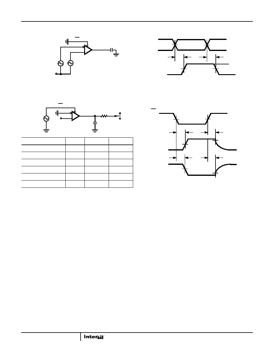
FIGURE 7A. TEST CIRCUIT
FIGURE 7B. MEASUREMENT POINTS
FIGURE 7. RECEIVER PROPAGATION DELAY AND DATA RATE
FIGURE 8A. TEST CIRCUIT
FIGURE 8B. MEASUREMENT POINTS
FIGURE 8. RECEIVER ENABLE AND DISABLE TIMES
Test Circuits and Waveforms (Continued)
SIGNAL
GENERATOR
R
RO
RE
A
B
15pF
SIGNAL
GENERATOR
VCM
RO
750mV
-750mV
tPLH
0V
VCC
0V
50%
tPHL
A
B
PARAMETER
DE
A
SW
tHZ
0
+1.5V
GND
tLZ
0
-1.5V
VCC
0
+1.5V
GND
0
-1.5V
VCC
0
+1.5V
GND
0
-1.5V
VCC
1k
GND
SW
SIGNAL
GENERATOR
R
RO
RE
A
B
15pF
VCC
RO
0V
1.5V
VOH
0V
1.5V
VOH - 0.5V
tHZ
RO
VOL
1.5V
VOL + 0.5V
tLZ
RE
OUTPUT LOW
tZL, tZL(SHDN)
tZH, tZH(SHDN)
3V
VCC
(Note 11)
OUTPUT HIGH
发布紧急采购,3分钟左右您将得到回复。
相关PDF资料
ISL32483EIBZ-T7A
IC TXRX RS485 FAULT PROT 14SOIC
ISL35822LPIK
IC CLOCK/DATA RECOVERY 192EBGA-B
ISL41334IRZ-T7A
IC TXRX RS232/485 DL 2PRT 40QFN
ISL43485IB-T
IC TXRX 1TX/1RX 3V RS-485 8-SOIC
ISL51002CQZ-110
IC FRONT END 10BIT VID 128-MQFP
ISL5314IN
IC SYNTHESIZER DIGITAL 48-MQFP
ISL55100AIRZ-T
IC COMP DRVR/WINDOW 18V 72-QFN
ISL55100BIRZ
IC COMP DRVR/WINDOW 18V 72-QFN
相关代理商/技术参数
ISL32472E
制造商:INTERSIL 制造商全称:Intersil Corporation 功能描述:Fault Protected, Extended Common Mode Range, RS-485/RS-422 Transceivers
ISL32472EIBZ
功能描述:IC TXRX RS485 FAULT PROT 8SOIC RoHS:是 类别:集成电路 (IC) >> 接口 - 驱动器,接收器,收发器 系列:- 产品培训模块:Lead (SnPb) Finish for COTS
Obsolescence Mitigation Program 标准包装:50 系列:- 类型:收发器 驱动器/接收器数:1/1 规程:RS422,RS485 电源电压:4.75 V ~ 5.25 V 安装类型:通孔 封装/外壳:8-DIP(0.300",7.62mm) 供应商设备封装:8-PDIP 包装:管件 产品目录页面:1402 (CN2011-ZH PDF)
ISL32472EIBZ-T
功能描述:IC TXRX RS485 FAULT PROT 8SOIC RoHS:是 类别:集成电路 (IC) >> 接口 - 驱动器,接收器,收发器 系列:- 产品培训模块:Lead (SnPb) Finish for COTS
Obsolescence Mitigation Program 标准包装:2,500 系列:- 类型:发射器 驱动器/接收器数:4/0 规程:RS422,RS485 电源电压:4.75 V ~ 5.25 V 安装类型:表面贴装 封装/外壳:16-SOIC(0.154",3.90mm 宽) 供应商设备封装:16-SOIC 包装:带卷 (TR)
ISL32472EIBZ-T7A
功能描述:RS-422/RS-485 接口 IC 8LD OVP -40+85 HI ES 5V RS HD+/-15V CMRS RoHS:否 制造商:Maxim Integrated 数据速率:1136 Kbps 工作电源电压:3 V to 5.5 V 电源电流:5.9 mA 工作温度范围:- 40 C to + 85 C 安装风格:SMD/SMT 封装 / 箱体:SOIC-28 封装:Tube
ISL32472EIBZ-T7A-CUT TAPE
制造商:INTERSIL 功能描述:ISL32452 Series 3.3 V 250 k/bps (-40 to +85?) RS-485/RS-422 Transceiver SOIC-8 制造商:Intersil 功能描述:ISL32452 Series 3.3 V 250 k/bps (-40 to +85
ISL32475E
制造商:INTERSIL 制造商全称:Intersil Corporation 功能描述:Fault Protected, Extended Common Mode Range, RS-485/RS-422 Transceivers
ISL32475EIBZ
功能描述:IC TXRX RS485 FAULT PROT 8SOIC RoHS:是 类别:集成电路 (IC) >> 接口 - 驱动器,接收器,收发器 系列:- 产品培训模块:Lead (SnPb) Finish for COTS
Obsolescence Mitigation Program 标准包装:50 系列:- 类型:收发器 驱动器/接收器数:1/1 规程:RS422,RS485 电源电压:4.75 V ~ 5.25 V 安装类型:通孔 封装/外壳:8-DIP(0.300",7.62mm) 供应商设备封装:8-PDIP 包装:管件 产品目录页面:1402 (CN2011-ZH PDF)
ISL32475EIBZ-T
功能描述:IC TXRX RS485 FAULT PROT 8SOIC RoHS:是 类别:集成电路 (IC) >> 接口 - 驱动器,接收器,收发器 系列:- 产品培训模块:Lead (SnPb) Finish for COTS
Obsolescence Mitigation Program 标准包装:2,500 系列:- 类型:发射器 驱动器/接收器数:4/0 规程:RS422,RS485 电源电压:4.75 V ~ 5.25 V 安装类型:表面贴装 封装/外壳:16-SOIC(0.154",3.90mm 宽) 供应商设备封装:16-SOIC 包装:带卷 (TR)